The purpose of this lab is to be able to use time of flight sesnors on the robot.Gaining an understanding of these sensors are integral to being able to let the robot drive at faster speeds.
Material List
1 x SparkFun RedBoard Artemis Nano
1 x USB cable
1 x 9DOF IMU sensor
2 x 4m ToF sensor
1 x QWIIC Breakout board
3 x Qwiic connector
1 x 650mAh battery from the RC car
1 x Ruler or graph paper
1 x Wire strippers/ Mini cutters
1 x Soldering iron
Prelab
As stated in the objective this lab's main focus will be on intergrating 2 time of flight sensors into our setup from lab 1 and 2.There is an issue with using these two sensors and it is centered around the
addresses of both devices. To use I2C with these devices at the same time at least one of the devices has to be a different address from the other. Since this is something that is programmable and has shut diwn
pins there are two approaches to this problem. The first one and the one I tried was simply changing the address of both sensors. When I conducted this approach I repeatedly encountered an issue with
being able to read in data from one or both of the sensors. I was not able to find the root cause of this error and instead fully implemented the approach using a shutdown pin. This appoarch allows for a
simplier and quick implementation that only need just a few more lines of code than th reading distance example given during the lab. In the end using the shutdown pin and changing one of the sensor's addresses allowed for me to fully
complete the lab.
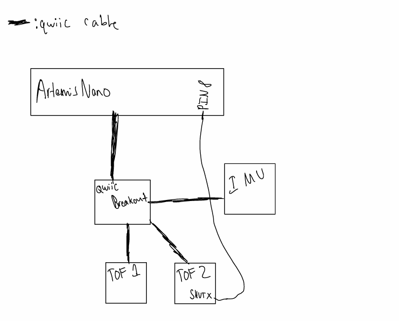
Additionally I needed to think about where to put my time of flight(TOF) sensors on my robot. I decided that having one sensor in the front and one sensor would be better. During a later lab every student will
be tasked with mapping out their surroundings with their robot and this approach would work well for that. The main drawback to this approach is being totally blind to the left and right of the robot. This might make it harder
to conduct object avoindace since the robot will have two potentially huge blinbd spots. A diagram of where I plan to place the TOF sensors is shown below:
Lab Tasks
Sensor Setup
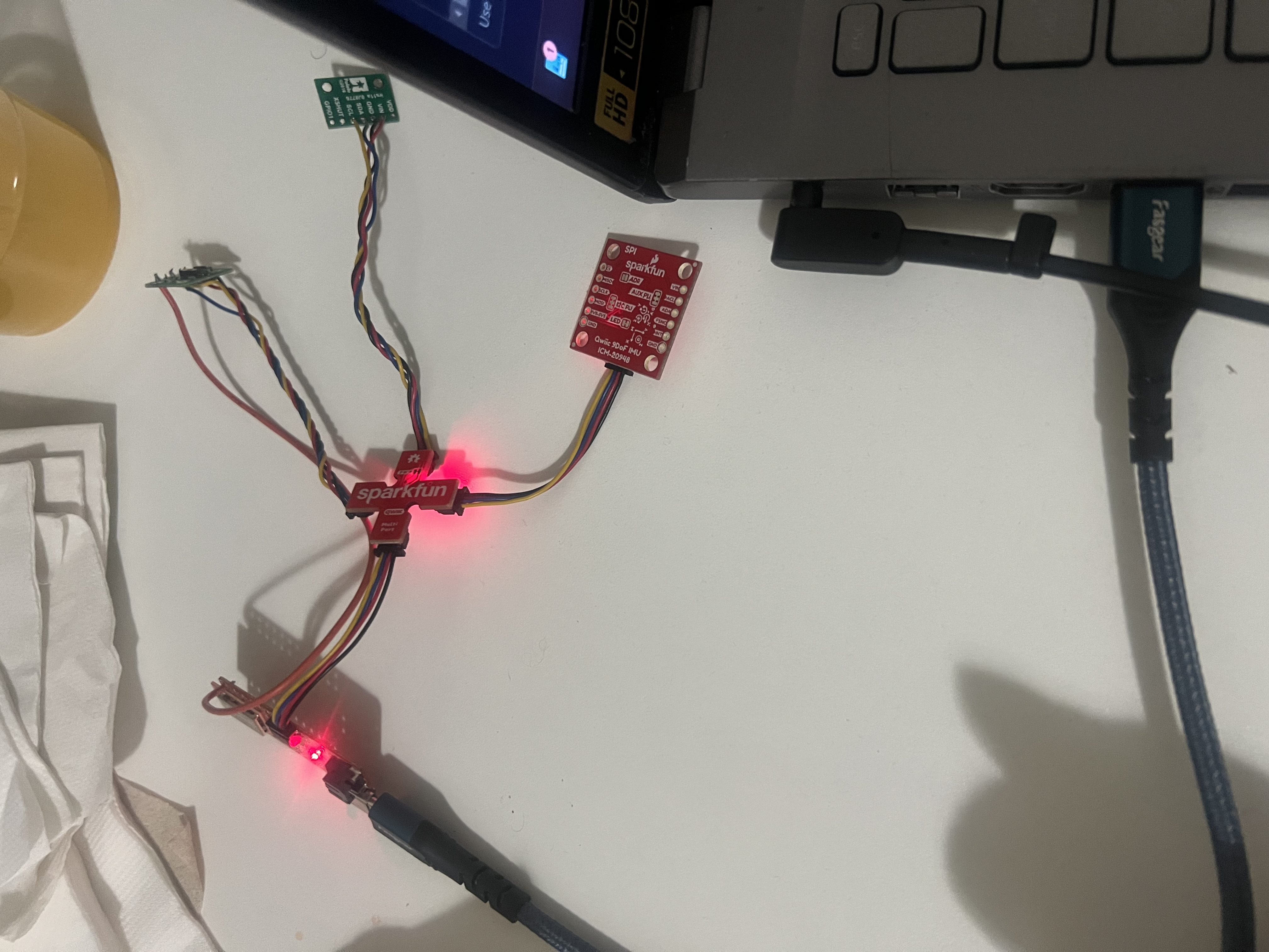
The sensor setup was pretty simple. I disconnected one end of a qwiic cable and sodered each wire to the corresponding hole on the TOF sensor. You can find a picture of the TOF sensors connected to a
qwiic breakout below:
Connected the ToF sensor to the QWIIC breakout board.
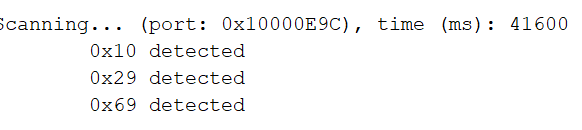
After connectinbg the sensors to the breakout, a I2C sweep was done on the breakout to make sure that the sensors are working and that it is displaying an address that makes sense. A picture of the sweep can be
found here:
Screenshot of Artemis scanning for I2C devices:
The detected I2C address was confirmed, ensuring proper communication.
Sensor Data Collection
Discussion and pictures of sensor data with chosen mode:
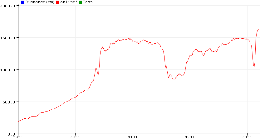
The TOF sensors come with 3 premade functions that change the range of what the sensors can see. The 3 functioncs are .setDistanceModeShort(), .setDistanceModeMedium(), and .setDistanceModeLong(). With each distance mode getting longer the better
the better the quaility of the data but the sampling rate if you were to increase the distance mode will drop causing the readings to be better. With that in mind and the max distance for the mode of the robot I chose
.setDistanceModeShort(). Since the max distance is within an acceptable range and we need to keep the vechile moving a at fast past at a later point, it made sense to use the short distance mode. A graph that shows the data I
gathered using this mode is shown below:r
Using Two ToF Sensors
I was able to use two TOF sensors at the same time. A video is shown of when I was able to do it. Note: I have a friend moving his hand infornt of the TOF sensors but he did not want to be filmed so that
is why what is moving infront of the sensors is not shown.
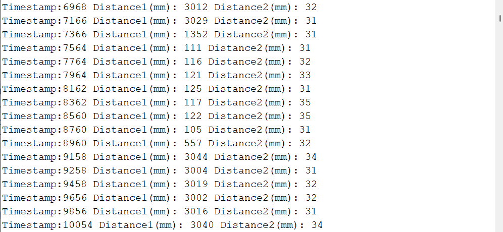
ToF Sensor Speed
When addressing the speed I took out the serial prints and waited for either of the sensors to be ready to send out the data but as you can see in the
picture below there is roughly a 200ms delay between each time the data is gathered. It seems that the limiting factor is how fast both sensor are ready to
collect data.
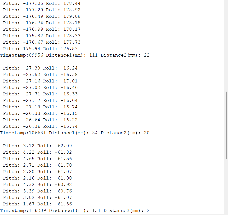
TOF and IMU being used together
After condcuting the speeds test I moved on to seeing if my code was able to still work while the IMU is connected to teh breakout. After a couple mntes I was
able to read data from each device allowing my robot to be able to tell its orienation and how close it is to objects around in a room. Below is a screenshot of the
data coming in from each device.
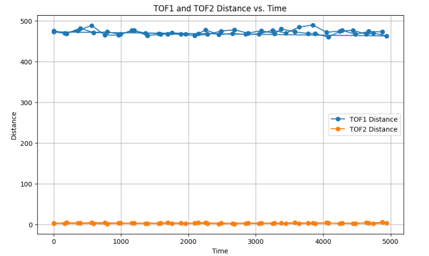
Time vs Distance
Graph of distance data sent over Bluetooth:
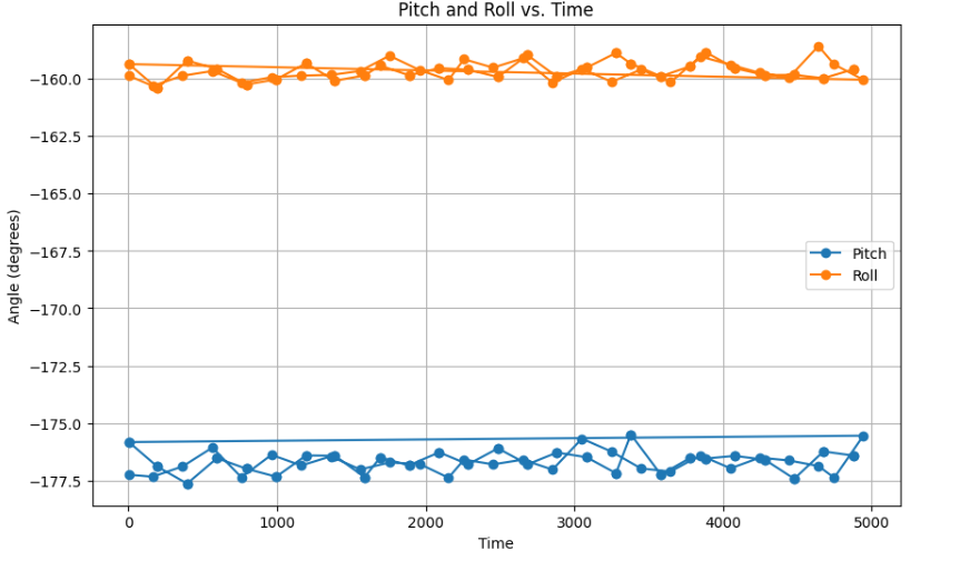
Time vs Angle
Graph of angle data sent over Bluetooth:
NOTE: The IMU and TOF sesnors were not moved when the data was gathered so what you are seeing is just the data of it sitting still.
Conclusion
This lab was able to allow me to become familir with soldering and empahize a focus on accuarcy and precision. It is clear that more of the tuning and filitering will come later since I imagine we will be introduced
to cleaner and simipler ways of extracting the data.