The purpose of this lab is to replace the hardware of the RC car with our own hardware and be able to conduct open loop actions to start the transition to automonous actions.
Diagram with intended connections between the motor drivers, Artemis, and battery (including specific pin numbers).
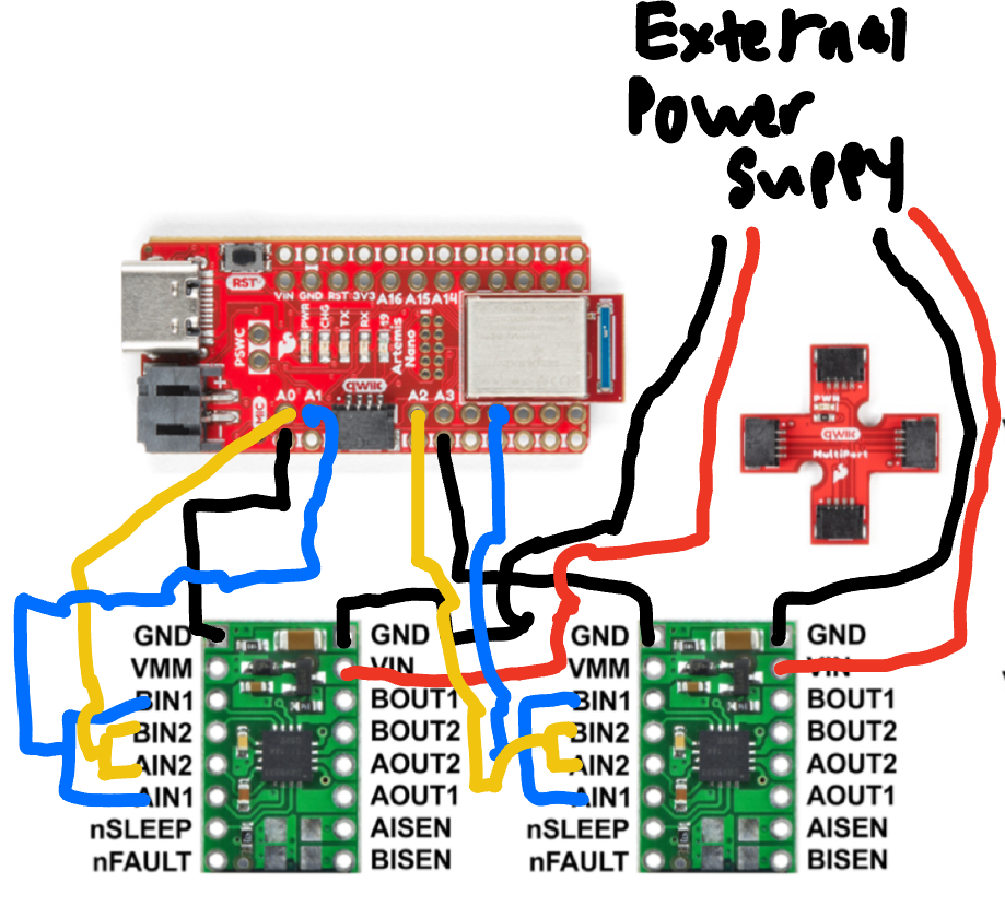
As can be seen in this diagram I decidced to make pins A0,A1,A2, and A5 the pins used for control. These pins are right next to a row of pins used for ground and they are close enough to each other that wiring them up was easy. The only issue I faced for using these pins for control is that when using the IDE these pins lose the A prefix and are simply numbers. Ex: A0 -> 0,A1 -> 1,etc. I was not aware of this at first so when I was using the oscilloscope to monitor the PWM signals I was not receiving anything at first.
The reason the Artemis and motor drivers are powered from separate batteries is due to current and eletrical noise. The motors require a much higher amount of current to drive them that spliting the current between the 2 motor drivers and the Artemis would most likely cause a lower amount of current to be supplied to the motor drivers. In terms of electrical noise when the componenets are sharing the same power and ground eltrical noise can be induced espically for components like the motors which are rapidly changing and has voltage and current spikes.
I do not have a picture of the settings used when I did my testing but I do have notes about the settings detailed after this section.
When deciding on the power supply setting I simply refernced the datasheet of the motor drivers. On page 5 under section 6.3 reconmenned operating conditions I saw that a minium of 2.7 volts were needed to allow the motors to turn. This led me to try this voltage first then increase or deacrese the voltage as needed. I was able to immediately see that the datasheet was correct that roughly 2.7V was needed to allow the motors to move and anything lower than that does not allow the motors to move. But, you can hear noises from the encoders around 2.5V signaling that a lower volatge can be used to start something with the motor drivers but as stated before to move the motors roughly 2.7V is needed.
    // Example PWM control for motor driver
    int MotorPin1 = 0;//Controls right side
    int MotorPin2 = 1;// Controls right side
    void setup() {
         pinMode(MotorPin1,OUTPUT);
         pinMode(MotorPin2,OUTPUT);
    }
    void loop() {
        //This section was to move the right side
        analogWrite(MotorPin1, 0);
        analogWrite(MotorPin2, 200);
        delay(5000);
        analogWrite(MotorPin1, 0);
        analogWrite(MotorPin2, 0);
    }
Short video of wheels spinning as expected.
    // Code running during test
    analogWrite(motorPin, 150);
Short video of both wheels spinning with battery power.
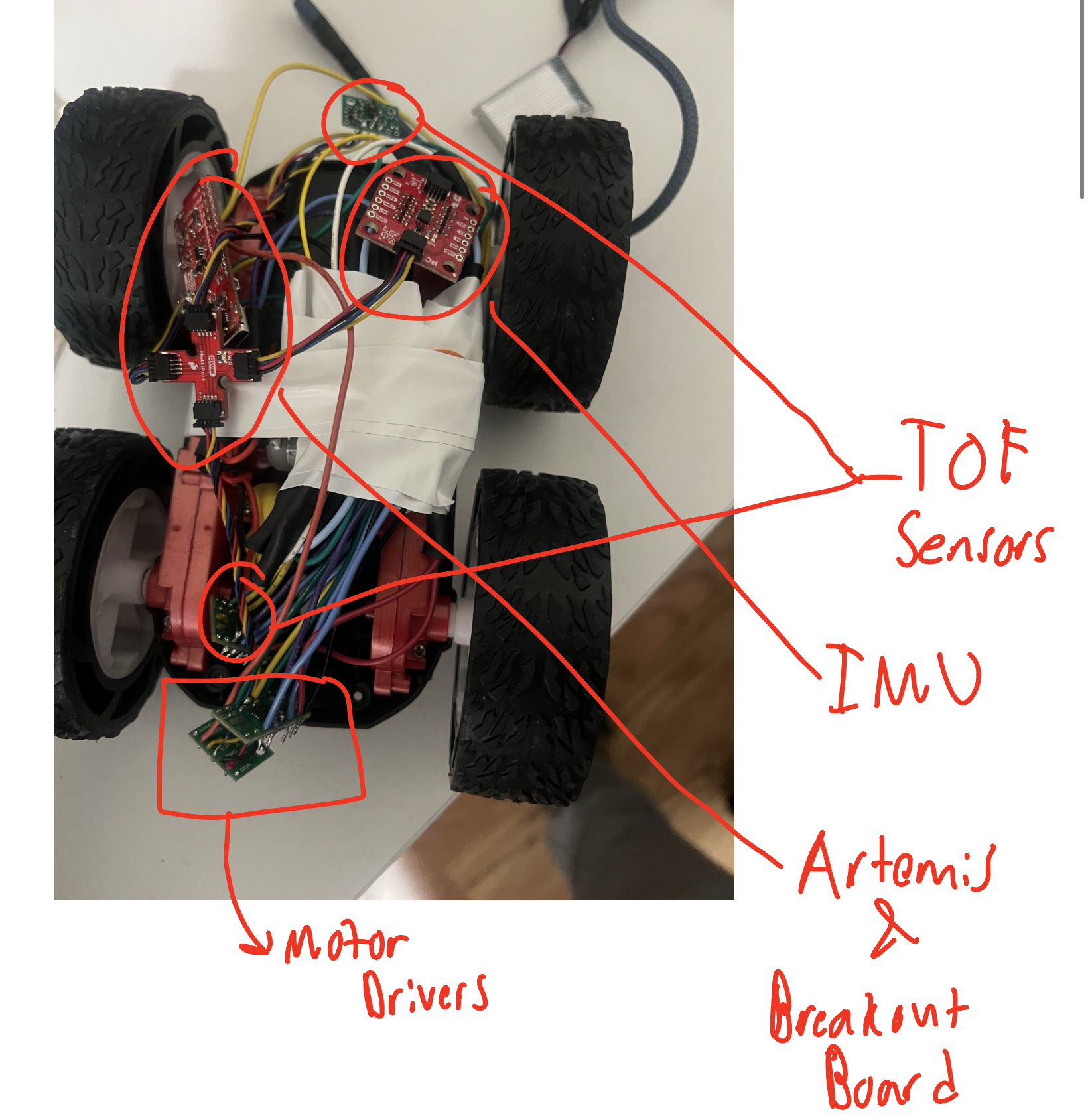
Shown below is a picture of all components secured in the car. I know that the way that the components are currently secured is not ideal but they will be more properly secured at a later date whether it is a time where it is absolutely needed or a time where I have free time.
The lowest PWM value I was able to send to get the motors to move was 75. I think this value is very dependent on the material of the surface the robot is driving on. When I tried that same value on the floor in my house I needed to bump up the value to 100. As will be shown later my calribration factor value did not need to be large. A video later showing the robot moving down a hallway shows that the wheels naturally stayed straight until the end when the right side dominated making the robot move to the left. Through a few trials I found that the calibration value was ____.
    // Example calibration factor implementation
    int leftMotorPWM = 150;
    int rightMotorPWM = 160; // Adjusted for balance
Video demonstrating open loop movement.
    // Example open loop movement code
    void loop() {
        static int counter = 0;
        analogWrite(MotorPin1, 0);
        analogWrite(MotorPin2, 100);
        analogWrite(MotorPin3, 150);
        analogWrite(MotorPin4, 0);
        delay(10);
        analogWrite(MotorPin1, 0);
        analogWrite(MotorPin2, 0);
        analogWrite(MotorPin1, 0);
        analogWrite(MotorPin2, 0);
        ++counter;

        if(counter > 300){
        while(counter > 300){
            analogWrite(MotorPin1, 0);
            digitalWrite(MotorPin2, 0);
            analogWrite(MotorPin3, 0);
            analogWrite(MotorPin4, 0);
            delay(5000);
        }
    }