Continuing from the previous lab I have now moved to put using the Bayes Filter in a real life sceme that mirrors the layout seen in lab 10.
First I needed to run the localization simulation to make sure the general logic of using the bayes filter was correct.
After this I had to measure out known positons within the layout of testing area. These mesaurements became the ground truth with can be seen below:
      (-3ft,-2ft)
      (0ft,3ft)
      (5ft,3ft)
      (5ft,-3ft)
After measuring out those points I converted them to meteres and placed them into the provided robot class making the position for the ground truth to be returned in this function here:
       def get_pose(self):
        """Get robot pose based on odometry

        Returns:
            current_odom -- Odometry Pose (meters, meters, degrees)
        """
        # If @ (-3,-2)
        # odom = (-0.914, -0.6096, 0)
        # gt = (-0.914, -0.6096, 0)
        # return odom, gt

        # If @ (0,3)
        # odom = (0.0, 0.914, 0)
        # gt = (0.0, 0.914, 0)
        # return odom, gt

        # # If @ (5,-3)
        # odom = (1.524, -0.914, 0)
        # gt = (1.524, -0.914, 0)
        # return odom, gt

        # If @ (5,3)
        odom = (1.524, 0.914, 0)
        gt = (1.524, 0.914, 0)
        return odom, gt
From here I was ready to move onto to gathering data at said points and developing a belief of where the robot thinks it is at. The robot needed to be placed in each spot and placed facing parallel to the x-axis. From there the robot needed to collect TOF data spin 20 degrees counterclockwise and collect another piece of data and repeat that process until it spin around a full 360 degrees and taken 18 distance measurements. Those values where placed into an array and converted to meters and used to calculte the belief of the robot.
Below is the code that was used to gather and process the TOF sensor data:
      def map_handler(uuid,byte_array):
      global time
      global dist1
      global dist2
      global angle
      s = ble.bytearray_to_string(byte_array).split(",")
      time.append(float(s[0].split(":")[1]))
      dist1.append(float(s[1].split(":")[1]))
      dist2.append(float(s[2].split(":")[1]))
      angle.append(float(s[3].split(":")[1]))

      def perform_observation_loop(self, rot_vel=120):
        """Perform the observation loop behavior on the real robot, where the robot does
        a 360 degree turn in place while collecting equidistant (in the angular space) sensor
        readings, with the first sensor reading taken at the robot's current heading.
        The number of sensor readings depends on "observations_count"(=18) defined in world.yaml.

        Keyword arguments:
            rot_vel -- (Optional) Angular Velocity for loop (degrees/second)
                        Do not remove this parameter from the function definition, even if you don't use it.
        Returns:
            sensor_ranges   -- A column numpy array of the range values (meters)
            sensor_bearings -- A column numpy array of the bearings at which the sensor readings were taken (degrees)
                               The bearing values are not used in the Localization module, so you may return a empty numpy array
        """
        sensor_bearings = np.zeros(18)
        map_tof_vals = []
        ble.start_notify(ble.uuid['RX_STRING'], map_handler)
        ble.send_command(CMD.MAP_ENVIRON, "")

        while(len(dist2) < 18):
            asyncio.run(asyncio.sleep(3))

        map_tof_values = [val / 1000 for val in dist1]
        ble.stop_notify(ble.uuid['RX_STRING'])
        sensor_ranges = np.array(map_tof_values)[np.newaxis].T
        print(sensor_ranges)

        return sensor_ranges, sensor_bearings
NOTE: SINCE IT WAS MENTIONED THAT SENSOR_BEARINGS WERE NOT NEEDED AN ARRAY FULL OF ZEROES WERE USED TO FIND THE BEARINGS.
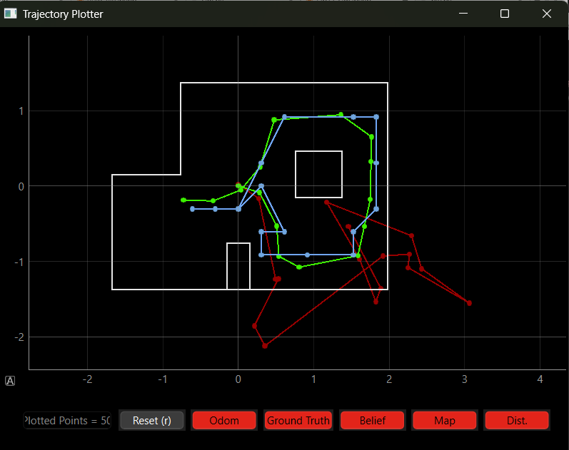
From here I made plots of the robot's belief and the ground truth. The plots at each position can be seen below. The blue dot is the robot's belief and the green dot is the ground truth:
(-3,-2)
_pic.png)
(0,-3)
_pic3.png)
(5,3)
_pic2.png)
(5,-3)
_pic.png)
I kept recieving very bad plots due to the robot not being able to spin an entire 360 degrees. The tape on 2 of my wheels would slightly peel off causing the robot to cut its spin shorter and then not move for the next reading so I had to intervene and give it slight nudges as it would spin. This is what caused some of the plots shown above to be off from the ground truth by a significant amount. Since I did not have time to remove the tape or trim it some of the data would be significantly off.
In the end the robot had a decnt belief of where it was at but if the tape spot it and messed up its rotation the data would become off by a larger amount as seen in (5,3) and (0,3)